
Products
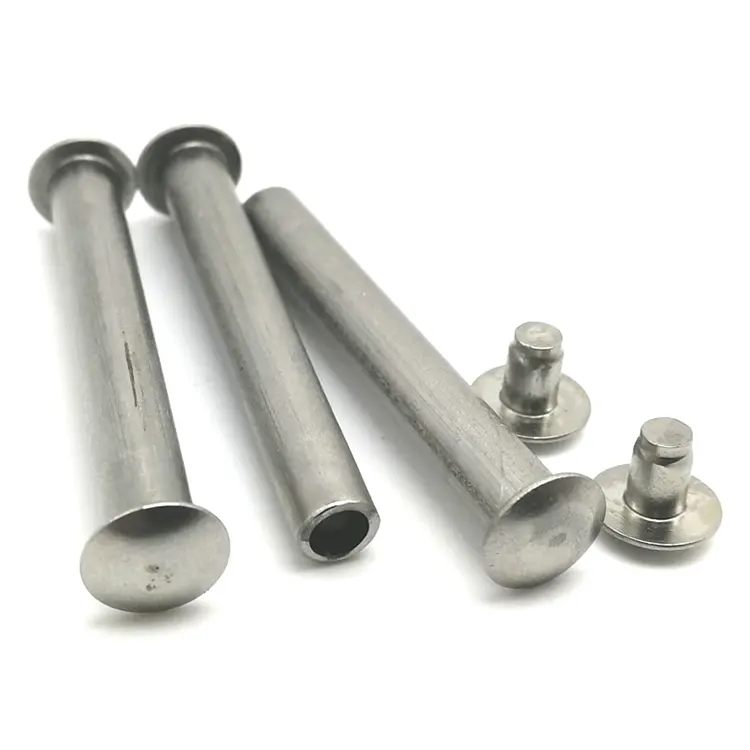
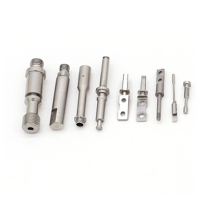
CNC Machined Components
A CNC machined component is rarely made on one machine. It is turned, then milled, then ground—and every time it moves, the datum can shift. Nuote Metals produces CNC machined components in China with one datum established at the first operation and referenced at every subsequent operation—turning, milling, grinding, and inspection. ±0.005mm on critical features.
Send Inquiry
Product Description
CNC Machined Components – The Datum Must Survive Every Operation
A CNC machined component is not a single-operation part. It is a sequence: turned on a lathe, milled on a machining center, ground on a grinder, inspected on a CMM. Each operation removes material, changes the stress state, and introduces variation. And each time the component is re-clamped, the datum can shift—the bore that was concentric after turning is 0.02mm off after milling, the face that was flat after milling is 0.01mm warped after grinding.
CNC machined components are judged by whether the features align after every operation—not just after the first one. The datum is the thread that holds the sequence together. If the datum shifts, the features do not align, and the component does not assemble—even if every individual operation met its tolerance.
At Nuote Metals, we produce CNC machined components with one datum established at the first operation and referenced at every subsequent operation. This article covers the multi-process challenge, the datum control method, and what to verify before accepting a component.
The Multi-Process Challenge – Where Components Lose Alignment
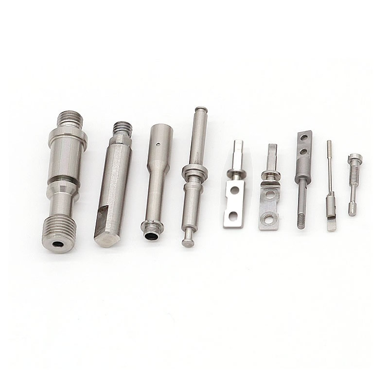
A component that requires turning, milling, and grinding passes through at least three machines and three setups. Each setup is a chance for the datum to shift.
| Operation | Typical Datum | Risk If Datum Shifts | Effect on Component |
|---|---|---|---|
| Turning | Face and bore | Bore not concentric to face | Mating shaft binds or leaks |
| Milling | Turned face and bore | Cross-hole not aligned to bore | Pin does not enter, or enters at an angle |
| Grinding | Turned face and bore | Ground diameter not concentric to bore | Bearing runs out, vibration |
| Inspection | Drawing datum | Features measured from different origins | Good parts rejected, bad parts accepted |
The risk is not the tolerance of any single operation—it is the relationship between operations. A bore that is ±0.01mm after turning is still ±0.01mm after milling—if the datum is the same. But if the milling fixture references the outer diameter instead of the bore, the cross-hole position shifts by the OD tolerance—and the component fails.
For CNC machined components, the datum is not a drawing formality—it is the physical reference that must be preserved from the first cut to the final inspection.
One Datum, Every Operation – How We Control the Sequence
We establish the datum at the first operation—typically the turned face and bore—and we reference that same datum at every subsequent operation. The fixture is designed around the datum, not around a convenient clamping surface.
Turning: The face and bore are machined in the same setup—the bore is concentric to the face by default. This is the datum.
Milling: The fixture clamps on the turned face and locates on the bore. The cross-holes and flats are machined relative to the bore—not the outer diameter. If the OD is out of round, the cross-hole is still aligned to the bore.
Grinding: The fixture clamps on the same face and locates on the same bore. The ground diameter is concentric to the bore—not to the previous OD.
Inspection: The CMM fixtures on the same face and bore. The features are measured from the same origin used in machining—not from a convenient surface.
Why this matters: A component with a 0.02mm OD tolerance and a 0.01mm cross-hole position tolerance can still assemble—if the cross-hole is referenced to the bore. The OD tolerance does not stack into the cross-hole position. The datum breaks the stack.
Standard reference: Datum practice follows ASME Y14.5 and ISO 5459. Dimensional tolerances follow ISO 2768-mK unless a tighter callout is specified.
The Equipment That Makes One-Datum Machining Possible
One-datum machining is not a process plan alone—it requires equipment that can hold the datum across operations.
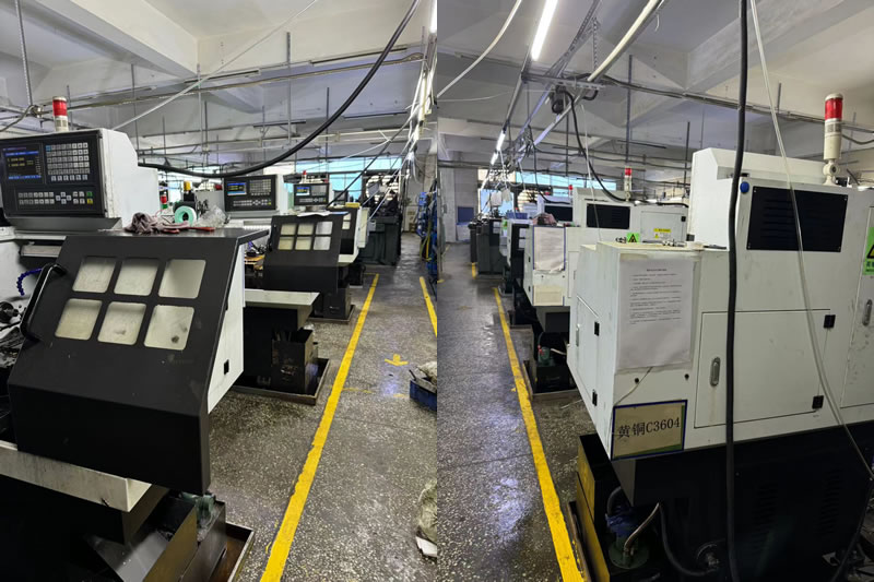
5-axis mill-turn centers (DMG MORI NHX 5000, Mazak Integrex): Turn and mill in one setup—the datum never leaves the chuck. For components with cross-holes, flats, and turned features, the mill-turn center eliminates the transfer between lathe and machining center.
CNC lathes with live tooling (Haas ST-20Y, Okuma Genos L): Turn, cross-hole, and tap in one setup—the datum is established at the face and bore, and the cross-hole is machined relative to it without re-clamping.
CMM with scanning probe (Zeiss Contura 7/10/6): Fixtures on the same datum used in machining—the inspection confirms the relationship between features, not just the individual dimensions.
In-process gauging: For critical features, the gauge is designed around the datum—the bore or the face—so the measurement reflects the assembly condition, not a convenient clamping surface.
For CNC machined components, the equipment is not a list of machines—it is a system that preserves the datum from the first cut to the final inspection.
A Real Example – Cross-Hole Alignment Saved by One Datum
A German hydraulic equipment manufacturer needed a 4140 valve body with a turned bore, a milled mounting face, and four cross-holes. The cross-holes had to be positioned within 0.02mm of the bore centerline. Their previous supplier turned the body, then milled the cross-holes referencing the outer diameter—the cross-hole position varied by 0.06mm, and 9% of components failed assembly.
What we did differently:
- Established the bore as the datum at turning—machined the bore and face in one setup.
- Milled the cross-holes on a 5-axis mill-turn center—the component never left the chuck, and the cross-holes were machined relative to the bore.
- Ground the bore after heat treatment using the same bore datum—the concentricity was preserved.
- Verified the cross-hole position on a Zeiss Contura CMM—fixtured on the bore datum, not the OD.
- Shipped 1,200 components with zero assembly failures.
A lesson we learned: Early in our multi-process program, we had a batch where the grinding fixture referenced a different surface than the turning fixture—3% of components failed concentricity. That batch was reworked at our cost, and we have since made the datum transfer checklist a mandatory step before any multi-process job starts.
Limitation: This one-datum approach is validated for components where the bore is accessible for fixturing at every operation. For components with internal features that cannot be accessed after assembly, the datum may need to be transferred—and the stack re-evaluated.
This is what CNC machined components should deliver: not just a component that meets each operation’s tolerance, but a component whose features align because the datum was preserved—not re-established at every setup.
Frequently Asked Questions
Q1: Why does one datum matter for multi-process CNC machined components?
A: Because every time the component is re-clamped, the datum can shift. A bore that is concentric after turning can be 0.02mm off after milling—if the milling fixture references the outer diameter instead of the bore. One datum—established at the first operation and referenced at every subsequent operation—breaks the tolerance stack. The features align because they are measured from the same origin, not because each operation happened to meet its own tolerance.
Q2: Can you machine a component complete in one setup?
A: For many components, yes—on a 5-axis mill-turn center. The turning, milling, cross-holes, and threads are machined without re-clamping, and the datum never leaves the chuck. For components that require heat treatment or grinding after machining, the datum is transferred to the grinding fixture—but it is the same datum, not a new one. The goal is to minimize the number of datum transfers, not to eliminate them at any cost.
Q3: How do you verify that the datum was preserved across operations?
A: We fixture the component on the same datum used in machining—the turned face and bore—and measure the critical features on a CMM. If the cross-hole position is within tolerance when measured from the bore, the datum was preserved. If it is within tolerance when measured from the OD but out when measured from the bore, the datum was lost—and the component may fail in assembly.
Q4: Does one-datum control add cost to the component?
A: It adds cost in fixturing and inspection time—the fixtures must be designed around the datum, and the CMM must be fixtured the same way. But it reduces cost in assembly—fewer components are rejected, fewer are reworked, and the assembly line does not stop. For CNC machined components with multiple features that must align, the total cost is lower with one-datum control—not higher. We provide a cost breakdown showing the fixturing and inspection cost against the expected assembly scrap reduction.
Send Inquiry
Please feel free to fill your inquiry in the form below. We will reply you in 24 hours.



X
We use cookies to offer you a better browsing experience, analyze site traffic and personalize content. By using this site, you agree to our use of cookies.
Privacy Policy