
Products
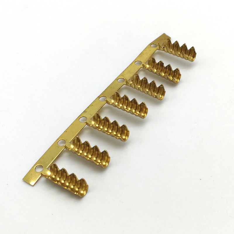
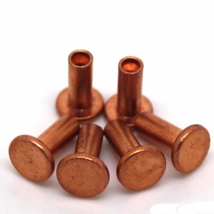
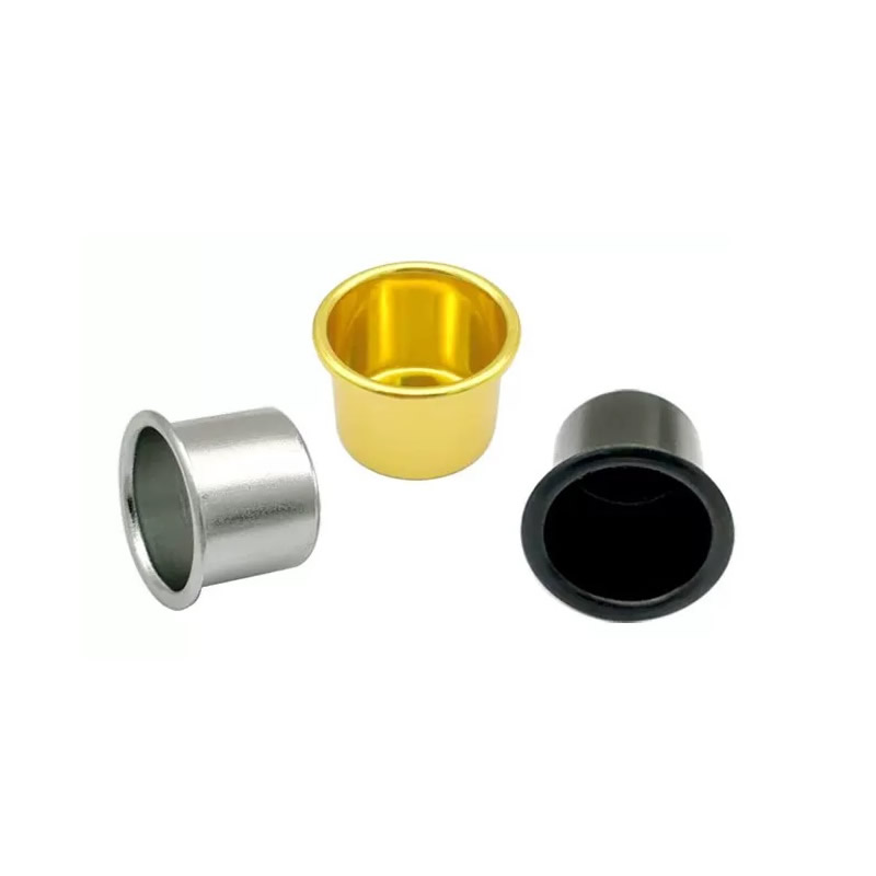
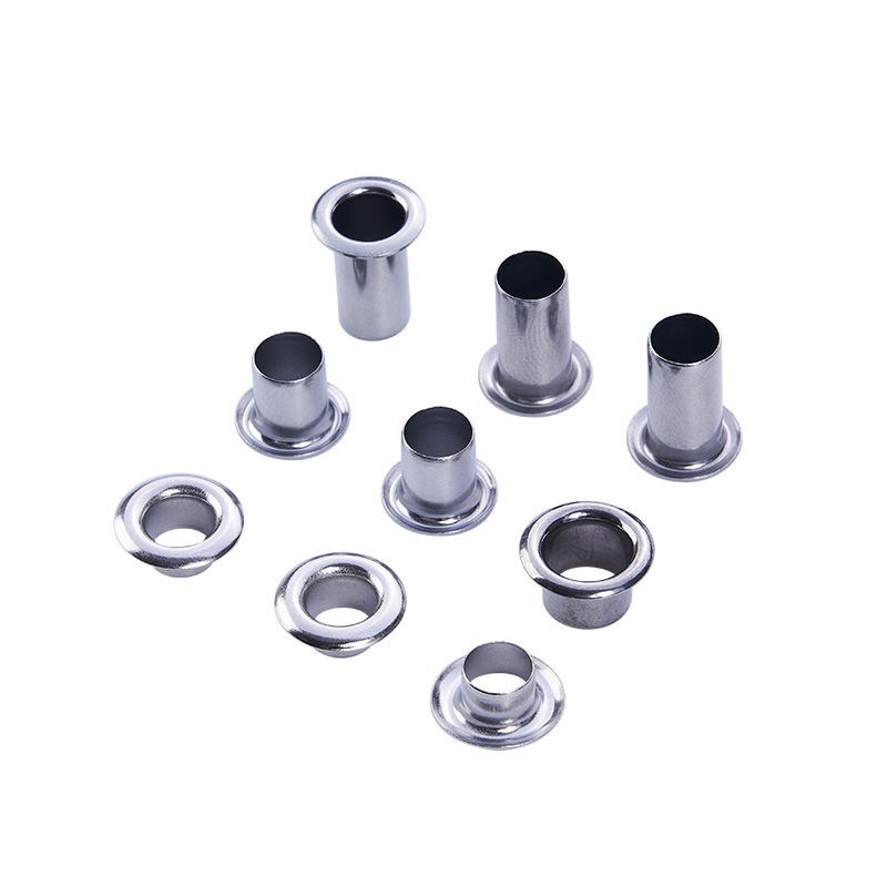
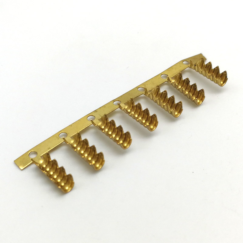
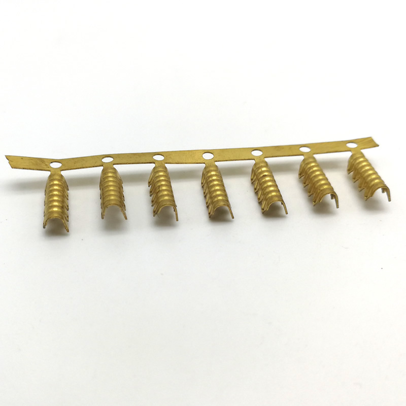
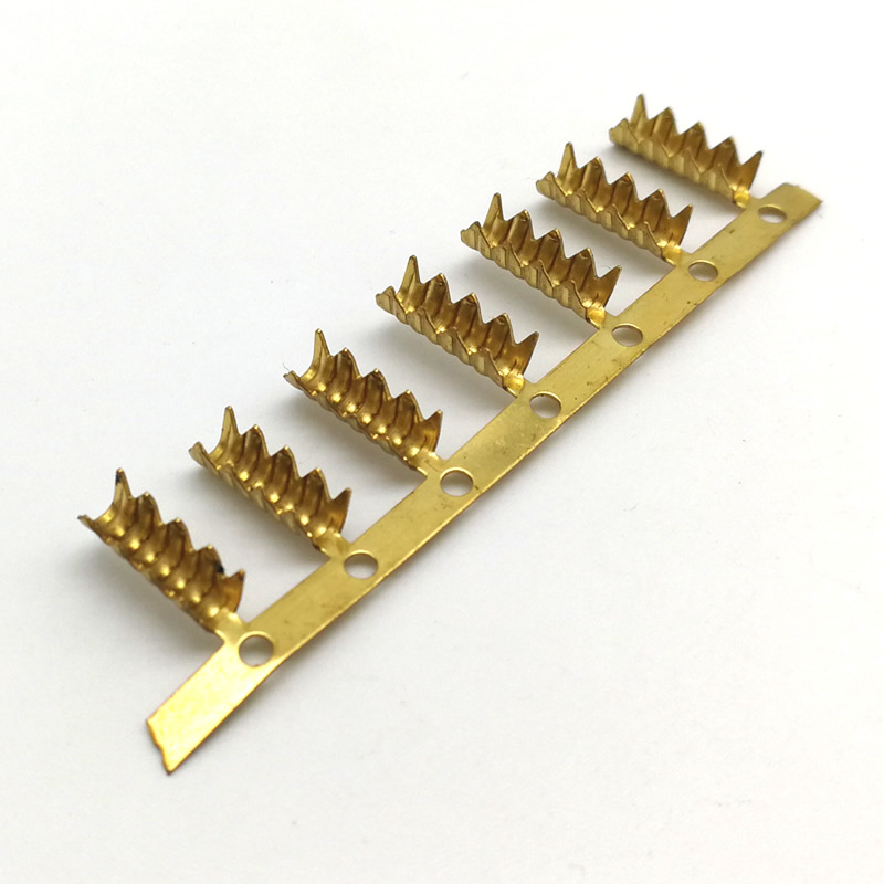
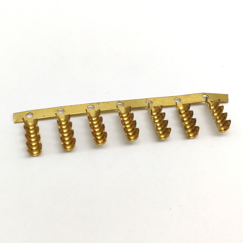
stamping terminals
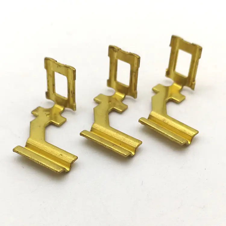
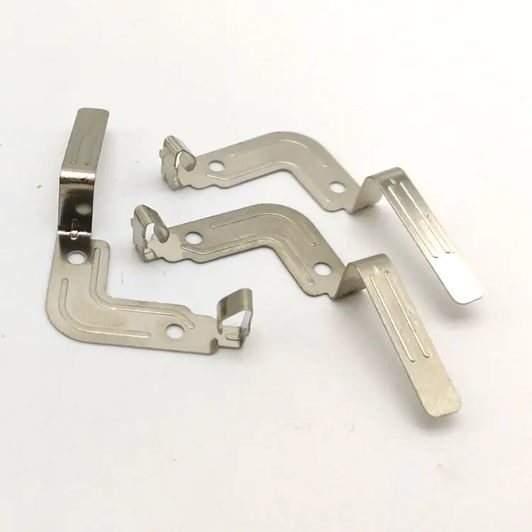
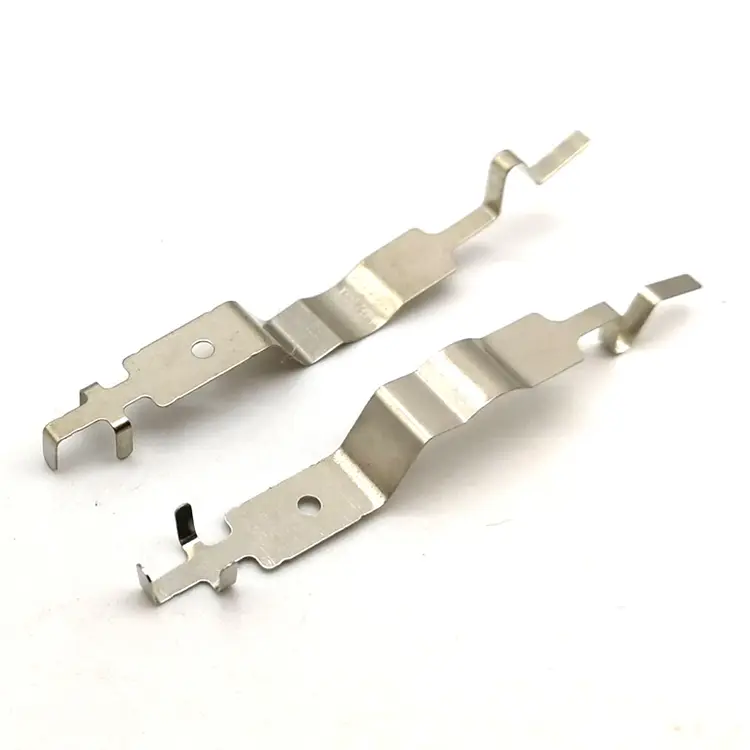
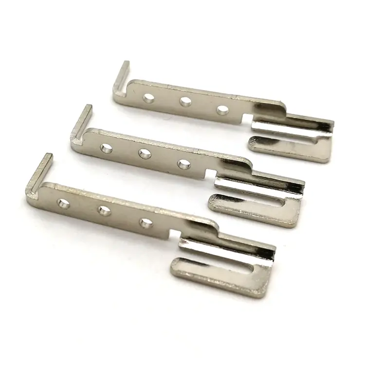
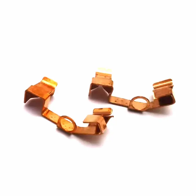
A terminal drawing specifies dimensions—beam length, beam thickness, contact curvature. But the terminal is judged by something the drawing rarely states: insertion force. A terminal that is 0.05mm too stiff will not insert; 0.05mm too soft will not hold. Nuote Metals produces custom stamping terminals in China with normal force and insertion force measured on the first article and verified on every batch—wound on reel for automated insertion. Brass, phosphor bronze, and copper. Reel-to-reel plating.
Send Inquiry
Product Description
Custom stamping terminals are continuous stamped parts—the strip feeds through a progressive die, the terminals remain attached to the carrier, and the reel is shipped to the customer's insertion machine. The terminal must meet three functional requirements: normal force (the contact pressure against the mating pin), insertion and withdrawal force (the effort to mate and unmate), and contact resistance (the electrical path through the contact interface). None of these appear on a standard dimensional drawing—and all three determine whether the connector works.
At Nuote Metals, we produce custom terminals with normal force and insertion force measured on the first article and verified on every batch. This article covers the three functional requirements, the geometry that controls them, the plating that preserves them, and the packaging that delivers them.
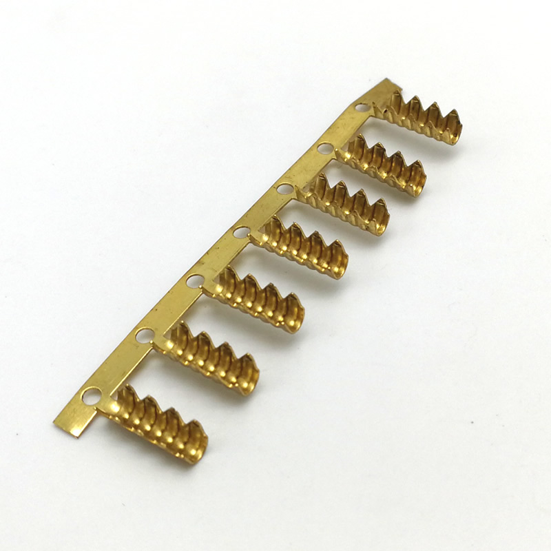
The Three Functional Requirements of a Terminal
A terminal is not a bracket with a bend. It is a spring that must deflect, return, and conduct—thousands of times.
| Functional Requirement | What It Means | Controlled By | Failure Mode |
|---|---|---|---|
| Normal force | Contact pressure against the mating pin | Beam length, beam thickness, contact curvature | Too low—intermittent contact; too high—insertion damage |
| Insertion / withdrawal force | Effort to mate and unmate | Normal force, lead-in chamfer, plating friction | Too high—operator cannot insert; too low—terminal releases |
| Contact resistance | Electrical path through the interface | Plating material, plating thickness, contact area | Too high—voltage drop, heat, signal loss |
Normal force is the pressure the spring beam exerts on the mating pin. It must be high enough to break through surface oxide and maintain contact—typically 1–3N for signal terminals, 3–8N for power terminals. Too low, and the contact becomes intermittent under vibration. Too high, and the insertion force becomes unacceptable—or the mating pin is damaged.
Insertion and withdrawal force is what the operator or the robot feels. It is the sum of the normal force, the friction coefficient of the plating, and the lead-in geometry. A terminal with 3N normal force and tin plating may require 15N insertion force—acceptable for a manual connector, too high for a high-density automated assembly.
Contact resistance is the electrical path through the contact interface. It depends on the plating material, the plating thickness, and the contact area. A tin-plated terminal may have 5–10mΩ contact resistance; a gold-plated terminal may have 1–3mΩ. The resistance must stay stable over the connector's life—not just at the first insertion.
For custom stamping terminals, the three requirements are linked: changing the beam thickness changes the normal force, which changes the insertion force, which changes the wear on the plating. The terminal is a system—not a list of dimensions.
The Geometry That Controls Normal Force
Normal force is determined by three geometric parameters—and each one has a trade-off.
Beam length. A longer beam deflects more easily—lower normal force for the same deflection. A shorter beam is stiffer—higher normal force. The beam length is set by the terminal pitch—the distance between terminals on the strip.
Beam thickness. A thicker beam is stiffer—higher normal force. A thinner beam is more compliant—lower normal force, but higher risk of yielding. The beam thickness is set by the strip thickness—which is also the crimp barrel thickness and the carrier thickness. The strip thickness cannot be optimized for the beam alone.
Contact point curvature. A smaller radius concentrates the contact force on a smaller area—higher contact pressure, lower contact resistance. A larger radius spreads the force—lower contact pressure, higher contact resistance, but lower wear on the plating.
The trade-off: A terminal that is stiff enough to maintain normal force may be too stiff to insert. A terminal that inserts easily may not maintain contact under vibration. The geometry is a balance—and the balance is verified by measuring the normal force and the insertion force on the first article, not by measuring the beam dimensions alone.
Standard reference: Terminal dimensions and tolerances follow IEC 60512 (connectors for electronic equipment) and EIA-364 (electrical connector test procedures) where specified. Insertion and withdrawal force are measured per EIA-364-13.
Plating – The Contact Resistance and Wear Layer
The plating is not cosmetic. It determines the contact resistance, the insertion force, and the wear life.
| Plating | Contact Resistance | Insertion Force (relative) | Wear Life | Best Application |
|---|---|---|---|---|
| Tin | 5–10 mΩ | Baseline | Moderate—wears through after 50–100 cycles | Consumer connectors, low-cost |
| Silver | 2–5 mΩ | Slightly lower than tin | Good—200–500 cycles | Power terminals, high-current |
| Gold (over nickel) | 1–3 mΩ | Lowest | Excellent—1,000+ cycles | Signal terminals, high-reliability |
Tin is the standard plating for consumer and automotive connectors—low cost, solderable, adequate contact resistance. But tin wears through after 50–100 insertion cycles—the base metal is exposed, and the contact resistance rises.
Silver offers lower contact resistance than tin and better wear life—used for power terminals and high-current applications. Silver tarnishes in sulfur environments—a nickel underlayer slows the tarnish.
Gold over nickel is the high-reliability choice—lowest contact resistance, longest wear life. The nickel barrier prevents copper diffusion; the gold layer maintains the contact resistance over 1,000+ cycles.
How we apply it: For custom stamping terminals, we use reel-to-reel plating—the terminals remain on the carrier and pass through the plating line as a continuous strip. Reel-to-reel plating is more consistent than piece-part plating—the current density is uniform, the thickness is uniform, and the terminals are not handled individually. The plating thickness is verified by XRF on every batch.
Packaging – Why Terminals Must Be on Reel
A terminal that is correct on the CMM can still fail at the customer's insertion machine—because the reel pitch is wrong, the orientation is reversed, or the carrier is too weak.
What the insertion machine requires:
Consistent pitch—the distance between terminals on the carrier must match the feeder pitch. A 0.1mm variation causes misfeed.
Consistent orientation—the terminals must face the same direction on the reel. A reversed terminal jams the feeder.
Carrier strength—the carrier must support the terminals through the feeder without stretching or breaking.
Splice integrity—when a reel runs out, the splice must be as strong as the carrier—and the pitch must be maintained across the splice.
For custom stamping terminals, the packaging is part of the specification—not an afterthought. We verify the reel pitch, the orientation, and the splice on every reel before shipping.
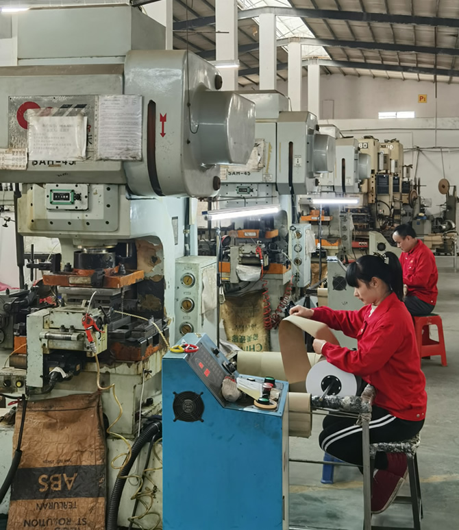
A Real Example – 0.64mm Pitch Terminal for Automotive Connector
A German automotive tier-1 supplier needed a custom stamping terminal for a 0.64mm pitch connector—normal force 2.5N ±15%, insertion force under 12N, contact resistance under 5mΩ, and reel pitch 4mm ±0.05mm.
The problem: Their previous supplier measured the beam dimensions and the crimp barrel—the terminals passed dimensional inspection, but 6% failed the insertion force test. The beam was 0.02mm too thick—the normal force was 3.2N, and the insertion force exceeded 15N.
What we did differently:
- Measured the normal force on the first article—not just the beam dimensions. The beam thickness was adjusted to bring the normal force to 2.4N.
- Verified the insertion force on a sample from every batch—12N maximum.
- Used reel-to-reel tin plating—uniform thickness, consistent friction coefficient.
- Verified the reel pitch on every reel—4mm ±0.03mm.
- Shipped 5 million terminals with zero insertion failures. The customer eliminated incoming inspection for insertion force.
This is what custom stamping terminals should deliver: not just a terminal that matches its drawing, but a terminal that inserts, holds, and conducts—because the normal force and the insertion force were measured, not assumed.
Frequently Asked Questions
Q1: What is the difference between a custom stamping terminal and a standard terminal?
A: A standard terminal is selected from a catalog—the geometry, the plating, and the reel pitch are fixed. A custom stamping terminal is designed for a specific connector—the beam geometry is matched to the required normal force, the plating is matched to the contact resistance and wear life, and the reel pitch is matched to the customer's insertion machine. The custom terminal is not a catalog part with a different label—it is a spring designed for a specific contact requirement.
Q2: How do you control insertion force on custom stamping terminals?
A: Insertion force is controlled by three variables: normal force (set by beam geometry), plating friction (set by plating material), and lead-in chamfer (set by the die). We measure the normal force on the first article, calculate the expected insertion force, and verify it on a sample from every batch. If the insertion force exceeds the specification, the beam thickness or the plating is adjusted—not the assembly procedure. For terminals, the insertion force is a measured value, not a calculated estimate.
Q3: Why is reel-to-reel plating better than piece-part plating?
A: Reel-to-reel plating keeps the terminals on the carrier through the plating line—the current density is uniform, the thickness is uniform, and the terminals are not handled individually. Piece-part plating requires handling, which can bend the beams, scratch the contacts, and produce uneven thickness. For custom stamping terminals with tight contact resistance requirements, reel-to-reel plating is the standard—the plating thickness is verified by XRF on every batch.
Q4: Can you provide DFM feedback on terminal geometry before I place an order?
A: Yes. Send us a drawing with the mating pin dimensions, the required normal force, the insertion force limit, and the contact resistance target. Our engineering team reviews the beam geometry for stress and deflection—confirming whether the proposed beam length and thickness can achieve the normal force without yielding, and whether the insertion force will meet the limit. For stamping terminals, the DFM review prevents the most common failure—a terminal that measures correctly and does not insert.
Send Inquiry
Please feel free to fill your inquiry in the form below. We will reply you in 24 hours.



X
We use cookies to offer you a better browsing experience, analyze site traffic and personalize content. By using this site, you agree to our use of cookies.
Privacy Policy