
Products
CNC Turned Components
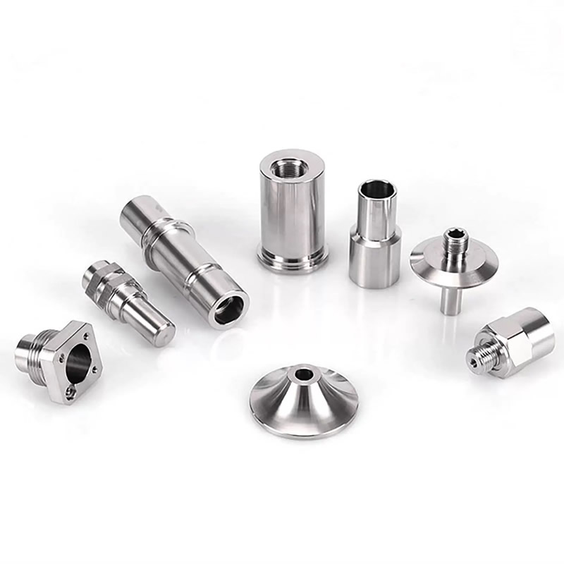
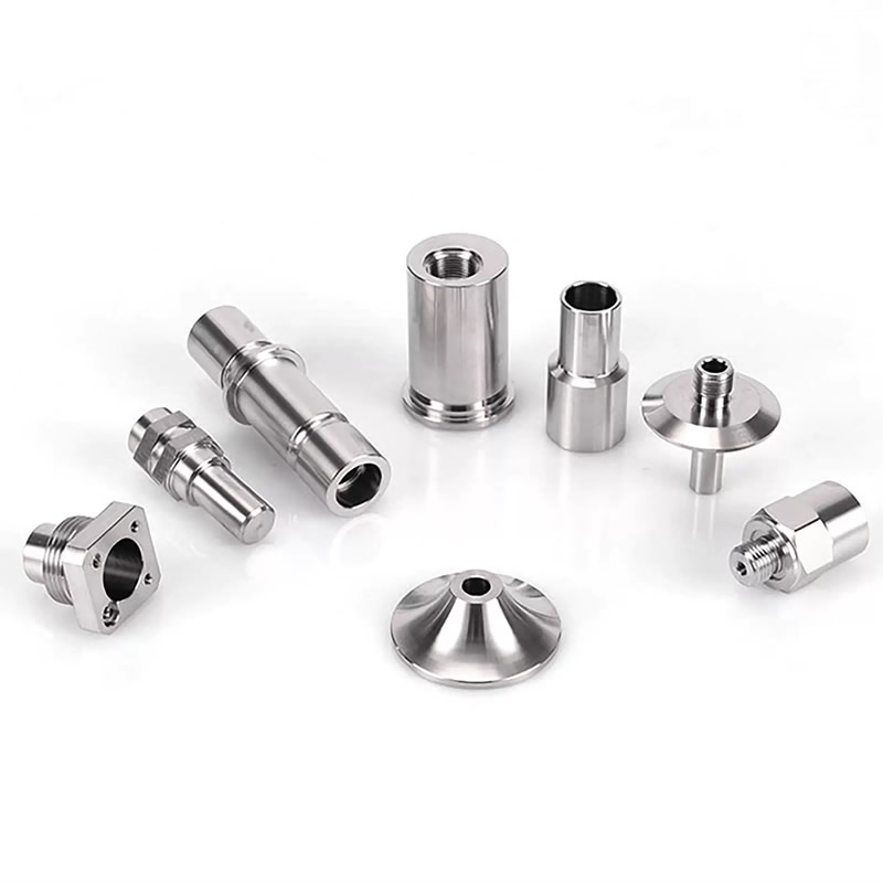
A CNC turned component is not judged by its own drawing—it is judged by whether it fits the part next to it. The bore must match the shaft, the face must seal against the housing, the thread must engage the port. Nuote Metals produces CNC turned components in China with interface dimensions and tolerance stacks managed for assembly—functional gauges simulate the mating part before the batch ships. ±0.005mm on critical interfaces.
Send Inquiry
Product Description
A turned component is rarely used alone. It is part of an assembly—a shaft in a bore, a spool in a sleeve, a fitting in a port. The component drawing specifies its dimensions. The assembly specifies its fit. And the fit depends on the interface—the bore diameter, the face flatness, the thread pitch, the chamfer lead-in. A component that meets every dimension on its own drawing can still fail the assembly because the interface tolerance stack was not managed.
CNC turning components are judged by the assembly—not by the CMM report. A bore that is ±0.01mm on its own drawing can be 0.02mm off when the mating shaft is at the other end of its tolerance. The interface is a stack—not a single dimension.
At Nuote Metals, we produce CNC turned components with interface dimensions and tolerance stacks managed for assembly. This article covers the three interface types, the stack calculation, the functional gauge verification, and what to check before accepting a turned component.
The Three Interface Types in Turned Components
A turned component mates with its neighbor through one of three interface types—and each has its own tolerance logic.
| Interface Type | Example | Critical Dimension | Failure If Stack Not Managed |
|---|---|---|---|
| Shaft-to-bore fit | Spool in sleeve, pin in hole | Clearance = bore min – shaft max | Interference (will not assemble) or rattle (leaks) |
| Face-to-face seal | Fitting against port face | Flatness and perpendicularity | Leak path at the seal |
| Threaded engagement | Fitting into port | Thread pitch diameter, lead-in chamfer | Cross-thread or insufficient engagement |
Shaft-to-bore fit is the most common interface. The clearance is the bore minimum minus the shaft maximum. If the clearance is negative, the parts interfere—they will not assemble. If the clearance is too large, the parts rattle or leak. The stack must be calculated from both component tolerances, not from the nominal.
Face-to-face seal depends on flatness and perpendicularity. A face that is flat but not perpendicular to the axis will seal on one side and gap on the other. The stack includes the face flatness, the perpendicularity, and the mating port face.
Threaded engagement depends on the pitch diameter and the lead-in chamfer. A thread that is within its own tolerance can still cross-thread if the lead-in chamfer is too small or the mating port is off-axis. The stack includes the thread tolerance and the chamfer.
For CNC turned components, the interface is a system—not a dimension.
The Tolerance Stack – Why Each Component Can Be “In Tolerance” and the Assembly Still Fails
A turned component and its mating part each have a tolerance. The assembly has a clearance or interference requirement. The stack is the sum of the component tolerances—and it must fit within the assembly requirement.
A simple example: Bore 10.00 ±0.02mm, shaft 9.96 ±0.02mm. The bore range is 9.98–10.02; the shaft range is 9.94–9.98. The minimum clearance is 9.98 – 9.98 = 0.00mm—interference at the worst case. The maximum clearance is 10.02 – 9.94 = 0.08mm—rattle. Both components are “in tolerance”—the assembly fails at the extremes.
How we manage it:
- Calculate the stack before quoting—identify the mating part tolerances and the assembly requirement.
- Tighten the component tolerance if the stack is too wide—or recommend a selective assembly.
- Verify with a functional gauge—a gauge that simulates the mating part at its worst-case tolerance.
For CNC turned components, the tolerance that matters is the one at the interface—not the one on the individual drawing.
Standard reference: Tolerance stacks follow ASME Y14.5 and ISO 2768-mK unless a tighter callout is specified. Interface dimensions are verified per ISO 1101 where geometric tolerances apply.
Functional Gauges – Simulating the Mating Part Before the Batch Ships
A CMM measures the component. A functional gauge measures the assembly. The difference is the mating part—the gauge is built to the worst-case mating tolerance, so a component that passes the gauge will assemble with any mating part in tolerance.
How we use functional gauges:
- Plug gauge for bore fit—sized to the maximum mating shaft. If the plug enters, the bore is large enough; if it wobbles, the bore is too large.
- Ring gauge for shaft fit—sized to the minimum mating bore. If the shaft enters, it is small enough.
- Seal face gauge—a flat plate with the same flatness as the mating port. If the component rocks, the seal face is not perpendicular.
What the gauge catches that the CMM misses: The CMM measures the component in isolation—the gauge measures it in the assembly condition. A bore that is within tolerance on the CMM can fail the plug gauge if the roundness is poor—the plug contacts the high points and does not enter.
For CNC turned components with critical interfaces, the functional gauge is the final verification—not the CMM.
Equipment: Zeiss Contura CMM for dimensional verification; custom functional gauges built to the mating part tolerance; Mitutoyo profilometer for seal face flatness.
A Real Example – Spool-and-Sleeve Assembly Failed at the Extreme
A German hydraulic equipment manufacturer needed a turned spool and sleeve assembly—spool diameter 12.00 ±0.005mm, sleeve bore 12.02 ±0.005mm. The calculated clearance was 0.01–0.03mm. Their previous supplier measured each component on the CMM—both were “in tolerance”—but 4% of assemblies seized at the minimum clearance.
What we did differently:
- Calculated the stack—the minimum clearance was 12.015 – 12.005 = 0.01mm, but the roundness of the bore consumed 0.005mm—the effective clearance was 0.005mm, and the spool seized.
- Tightened the bore roundness to 0.002mm—the effective clearance became 0.008mm minimum.
- Built a functional plug gauge sized to the maximum spool diameter—every sleeve was gauged before shipping.
Shipped 3,000 assemblies with zero seizure failures.
A lesson we learned: Early in our turned component program, we shipped a batch of sleeves that passed the CMM but failed the plug gauge—the roundness was within the drawing, but the plug could not enter. Since then, every interface with a clearance under 0.02mm is verified with a functional gauge before shipping.
Limitation: The functional gauge is validated for clearance 0.005–0.05mm. For tighter clearances, the gauge tolerance becomes a significant part of the stack—selective assembly may be required.
This is what CNC turned components should deliver: not just a component that measures correctly on its own drawing, but a component that assembles with its mating part—because the interface stack was managed and the gauge simulated the assembly.
Frequently Asked Questions
Q1: How do I calculate the tolerance stack for a turned component interface?
A: Start with the assembly requirement—the minimum clearance or maximum interference. Then add the component tolerances: bore minimum minus shaft maximum for clearance. If the result is negative, the assembly interferes at the extreme. For CNC turned components, we calculate the stack before quoting and recommend tightening the component tolerance if the stack is too wide—or selective assembly if it cannot be tightened.
Q2: What is a functional gauge, and why is it better than a CMM for interfaces?
A: A functional gauge simulates the mating part at its worst-case tolerance. A plug gauge sized to the maximum shaft diameter will not enter a bore that is too small—even if the bore is within its own tolerance. The CMM measures the component in isolation; the gauge measures it in the assembly condition. For CNC turning components with critical interfaces, the gauge is the final verification.
Q3: Can you manage the interface stack if I provide the mating part drawing?
A: Yes. Send the component drawing and the mating part drawing with the assembly clearance requirement. Our engineering team calculates the stack, identifies the risk at the extremes, and recommends the component tolerance or the gauge specification. For CNC turned components where the stack cannot be managed with standard tolerances, we recommend selective assembly or a design change.
Q4: What documentation comes with an order of CNC turned components?
A: Every order includes a dimensional report with actual measured values on critical interfaces, material certificates, and functional gauge results where specified. For regulated industries, PPAP documentation is available. The report shows the interface dimensions and the gauge result—so you can confirm the component will assemble, not just that it measures correctly.
Send Inquiry
Please feel free to fill your inquiry in the form below. We will reply you in 24 hours.



X
We use cookies to offer you a better browsing experience, analyze site traffic and personalize content. By using this site, you agree to our use of cookies.
Privacy Policy