
Products
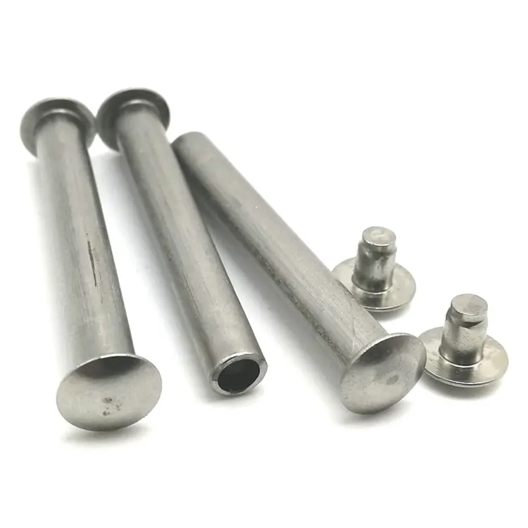

Precision Metal Stamping Parts
A precision stamping die costs three times a standard die—because the die is machined to a fraction of the part tolerance, not to the tolerance itself. Nuote Metals produces precision metal stamping parts in China with slow-wire EDM dies (±0.003mm), coordinate-ground punches, and presses verified for slider parallelism before every production run. ±0.02mm on critical features. PPAP and Cpk documented.
Send Inquiry
Product Description
A standard stamping die is machined to the part tolerance—if the drawing says ±0.05mm, the die is built to ±0.05mm. A precision stamping die is machined to a fraction of the part tolerance—if the drawing says ±0.02mm, the die is built to ±0.005mm. The die costs more because the machining time is longer, the EDM is slower, and the inspection is more frequent. But the die leaves tolerance for the press, the material, and the tool wear—so the part holds its tolerance across the batch, not just at the first article.
Precision metal stamping parts are not standard stampings with a tighter inspection plan. They are parts produced on a tooling system where the die accuracy, the press accuracy, and the in-die verification are all matched to the final tolerance. A die machined to ±0.05mm cannot produce a part with ±0.02mm position—the die error consumes the tolerance before the press strokes.
At Nuote Metals, we produce precision metal stamped parts by matching die accuracy, press accuracy, and in-die verification. This article covers the tooling system, the trial adjustments that make it work, and what to verify before accepting a precision stamping.

Die Accuracy – Slow-Wire EDM and Coordinate Grinding
The die is the first source of precision. A die that is machined to ±0.01mm cannot produce a part with ±0.02mm position—the die error consumes half the tolerance before the press even strokes.
How we build precision dies:
- Slow-wire EDM (Sodick AQ series) for die inserts and punches—position accuracy ±0.003mm, surface finish Ra 0.2μm.
- Coordinate grinding for punch and die profiles—profile accuracy ±0.002mm, edge sharpness controlled.
- Closed-loop wire EDM control—the wire position is corrected in real time, so the die contour matches the program, not the machine's drift.
- Die clearance matched to the material—calculated for the specific material and thickness, not a standard percentage.
Why it matters for precision metal stamping parts: A die built to ±0.01mm leaves ±0.01mm for the press and the material. A die built to ±0.003mm leaves ±0.017mm—enough to hold the part tolerance even when the press and material vary. The die accuracy is not a cost to minimize—it is the foundation of the tolerance.
Press Accuracy – What Must Be Verified Before Every Production Run
A precise die on an imprecise press produces imprecise parts. The press must hold its parallelism across the bed, repeat its bottom dead center at every stroke, and resist thermal growth during production.
| Press Parameter | What It Affects | Precision Requirement | How We Verify |
|---|---|---|---|
| Slider parallelism | Flatness, bend angle | ≤0.02mm across the bed | Hamar Laser alignment before production |
| Bottom-dead-center repeatability | Thickness, coining depth | ≤0.01mm stroke-to-stroke | Linear encoder on the slide (±0.001mm) |
| Thermal growth | Clearance, burr height | ≤0.01mm over 8 hours | Temperature sensors on the frame |
| Feed accuracy | Hole position | ±0.01mm per pitch | Servo feed with linear encoder |
Slider parallelism determines whether the punch enters the die evenly. A press with 0.05mm tilt produces a part that is 0.05mm thinner on one side—the flatness and the bend angle cannot meet a precision tolerance. We verify parallelism with a laser alignment system before production and after any die change.
Bottom-dead-center repeatability determines the coining depth and the final thickness. A press that varies by 0.02mm from stroke to stroke produces a part that is 0.02mm thicker at one end of the batch than the other. We monitor the stroke with a linear encoder—not a mechanical stop.
Thermal growth changes the clearance as the press warms. A press that grows 0.02mm over an 8-hour shift changes the die clearance by 0.02mm—and the burr height changes with it. We monitor frame temperature and adjust the die clearance when the temperature drifts beyond the set point.
For precision metal stamping parts, the press is not a commodity—it is a precision instrument that must be verified and monitored.
Trial Adjustments – What We Actually Change When the First Article Fails
A precision die does not produce a precision part on the first stroke. The trial stage is where the tolerance is achieved—by measuring the first article, identifying the source of the error, and adjusting the die or the press.
A typical trial sequence for a ±0.02mm position tolerance:
- First trial: Position measures ±0.035mm. The error is larger than the tolerance.
- Root cause: The die insert was machined to ±0.003mm, but the press parallelism was 0.03mm—the press was tilting the punch.
- Adjustment 1: Laser-align the press slide—parallelism reduced to 0.012mm.
- Second trial: Position measures ±0.025mm. Closer, but still out of tolerance.
- Root cause: The feed length varied by 0.008mm per pitch—the servo feed was not tuned to the strip mass.
- Adjustment 2: Tune the servo feed profile—feed accuracy improved to ±0.003mm.
- Third trial: Position measures ±0.015mm. Within tolerance.
- Production: In-die gauging pins installed at the piercing station—the press stops if the position drifts beyond 0.015mm.
What this shows: The precision is not in the die alone—it is in the trial adjustments that match the die to the press, and the press to the material. For precision stamping parts, the trial stage is not a formality—it is where the tolerance is actually achieved.
In-Die Verification – Measuring the Part Before It Is Cut Off
A precision stamping cannot be verified after the fact—by the time the part is measured, the die has already produced thousands of parts. The verification must happen in the die, before the part is cut off.
What we use in-die:
- In-die gauging pins – a pin engages the pierced hole at a defined station; if the hole is out of position, the pin does not enter, and the press stops.
- Tonnage monitoring – a load sensor on the die detects a missing part, a double blank, or a worn punch; the press stops before the die is damaged.
- Vision inspection at the last station – a camera measures critical features before the part drops; out-of-spec parts are rejected by an air blast.
Why in-die verification matters for precision metal stamping parts: At 200–600 strokes per minute, a tool wear event can produce hundreds of out-of-spec parts before the next sample is measured. In-die verification catches the drift at the stroke where it occurs—not at the end of the batch.
A Real Example – 0.5mm Stainless Surgical Clip with ±0.02mm Position
A US medical device manufacturer needed a 0.5mm stainless surgical clip with a ±0.02mm hole position, a 0.03mm flatness, and a 0.02mm burr limit. Their previous supplier machined the die to ±0.02mm and ran it on a standard press—the position varied by ±0.04mm, and 8% of parts failed assembly.
What we did differently:
- Re-machined the die inserts with slow-wire EDM—position accuracy ±0.003mm.
- Laser-aligned the press before production—slider parallelism 0.015mm across the bed.
- Tuned the servo feed to the 0.5mm stainless strip—feed accuracy ±0.003mm.
- Installed in-die gauging pins at the piercing station—the press stopped when the position drifted beyond 0.015mm.
- Verified burr height with an optical comparator every 200 pieces—0.015mm or better.
- Limitation: This approach is validated for material thickness ≥0.3mm. For thinner gauges, the strip deflects under the gauging pin force and the in-die verification becomes unreliable—those parts require optical inspection at the exit, not in-die gauging.
- Shipped 1.2 million pieces with zero assembly failures. The customer eliminated incoming inspection for position and flatness.
This is what precision metal stamping parts should deliver: not just a part that measures correctly at the first article, but a part that holds its tolerance across the batch—because the die, the press, and the in-die verification were matched to the tolerance, not the drawing.

Frequently Asked Questions
Q1: What is the tightest tolerance you can hold on precision stamping parts?
A: Our standard precision tolerance is ±0.02mm on hole position, ±0.03mm on flatness, and ±0.3° on bend angle. Tighter tolerances—±0.01mm on position—are achievable with in-die gauging, a die machined to ±0.003mm, and a press verified for parallelism. However, tighter tolerance means higher cost: the die takes longer to machine, the press runs slower, and the inspection is more frequent. For precision metal stamped parts, we review the tolerance and the volume before quoting—not after the first article fails.
Q2: What happens if my tolerance is tighter than ±0.02mm?
A: We review the tolerance and the feature before quoting. If the tolerance is tighter than our standard precision capability, we have three options: (1) In-die gauging—the die measures the feature before the part is cut off, and the press stops if it drifts. (2) Secondary operation—the feature is machined after stamping, which adds cost but holds tighter tolerance. (3) DFM recommendation—we suggest a design change that relaxes the tolerance without affecting function. For precision stamping parts, we do not promise a tolerance we cannot hold—we tell you which option is viable before you place the order.
Q3: What drives the cost of precision metal stamping parts?
A: Three factors: die accuracy, press time, and in-die verification. A die machined with slow-wire EDM and coordinate grinding costs more than a standard die—but it leaves tolerance for the press and the material. In-die gauging adds tooling cost but eliminates the scrap from a drift that is not caught until the next sample. For precision metal stamped parts, the cost is driven by the tooling system—not the material alone. We provide a cost breakdown with the quote—so you can see which element is driving the price.
Q4: Can you provide DFM feedback before I place an order?
A: Yes. Send us a drawing with the material, thickness, tolerance, and volume. Our engineering team reviews the part for die feasibility—position tolerance, flatness, burr height, and feature size—and returns a written DFM report with the quote. For precision metal stamping parts with tolerances tighter than ±0.02mm, we may recommend a first article or a trial run before committing to production tooling. This prevents the most common cost surprise—a die that is built and then modified because the tolerance was not achievable.
Send Inquiry
Please feel free to fill your inquiry in the form below. We will reply you in 24 hours.



X
We use cookies to offer you a better browsing experience, analyze site traffic and personalize content. By using this site, you agree to our use of cookies.
Privacy Policy