
Products
Deep Drawn Metal Stamping
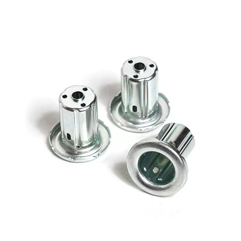
A deep drawn part fails in one of two ways—the flange wrinkles, or the sidewall tears. Both are controlled by the same three variables: blank-holder force, die radius, and lubrication. Nuote Metals produces deep drawn metal stampings in China with these variables matched to each material and draw stage. Cups, shells, and housings from 0.1mm to 6.0mm thick. PPAP documented.
Send Inquiry
Product Description
A deep drawn part fails in one of two ways. The flange wrinkles—the material buckles because the blank holder is not holding it flat. Or the sidewall tears—the material stretches beyond its forming limit because the punch force is too high and the die radius is too sharp. Wrinkling and tearing are opposite failures: one comes from too little restraint, the other from too much force.
Deep drawn metal stamping is the process of balancing those two failures—holding the flange flat enough to prevent wrinkling, while allowing the material to flow into the die without tearing the sidewall. The balance is controlled by three variables: blank-holder force, die radius, and lubrication. When all three are matched to the material and the draw stage, the part draws cleanly. When one is wrong, the part fails—and the failure mode tells you which variable to change.
At Nuote Metals, we produce deep drawn metal parts with blank-holder force, die radius, and lubrication matched to each material and draw stage. This article covers the two failure modes, the three variables, and what to verify before accepting a deep drawn part.

Wrinkling vs. Tearing – How to Read the Failure
The failure mode tells you which variable is wrong. A wrinkled flange and a torn sidewall are not the same problem—and the fix is not the same.
| Failure Mode | Where It Appears | Root Cause | What to Adjust |
|---|---|---|---|
| Flange wrinkling | Outer edge, between blank holder and die | Blank-holder force too low—or too high | Adjust blank-holder force to match the stage |
| Sidewall tearing | Punch nose, bottom corner | Die radius too sharp, friction too high | Increase die radius, improve lubrication |
| Wall thinning | Punch nose, sidewall | Draw ratio too aggressive for the material | Reduce draw ratio per stage |
| Orange peel | Sidewall surface | Coarse grain structure, insufficient anneal | Verify material grain size, anneal before draw |
Flange wrinkling occurs when the blank holder does not control the flange. Too little force—the material buckles. Too much force—the material cannot flow, and the sidewall tears in the next draw. The force must be matched to the stage.
Sidewall tearing occurs at the punch nose—the point of highest strain. The causes are a sharp die radius, high friction, or an aggressive draw ratio. The fix is not more blank-holder force—that makes the tear worse.
Wall thinning is a precursor to tearing—the wall thins before it tears. If the wall thickness at the punch nose drops below 80% of the blank thickness, the part is at risk in the next draw stage.
For these parts, the failure mode is the diagnostic—it tells you which variable to change. A supplier who increases blank-holder force to fix a tear will make the tear worse. A supplier who reduces force to fix a wrinkle will make the wrinkle worse.
Variable 1 – Blank-Holder Force: The Wrinkle Control
The blank holder holds the flange flat while the punch pushes the material into the die. The force must be high enough to prevent wrinkling—but low enough to allow the material to flow inward without tearing.
How blank-holder force changes with material and stage:
- First draw – highest force—the flange is largest and most prone to wrinkling.
- Second draw – lower force—the flange is smaller and the material is already work-hardened.
- Stainless steel – higher force than carbon steel—stainless work-hardens faster and resists flow.
- Aluminum – lower force than steel—aluminum flows more easily and wrinkles less.
How we control it:
- Hydraulic blank-holder cushion with pressure control—not a mechanical spring.
- Force set per draw stage—not a single setting for the whole sequence.
- In-die force monitoring—a load cell detects a change in force and signals the press to adjust.
In this operation, the blank-holder force is not a single number—it is a profile that changes with the draw stage and the material.
Variable 2 – Die Radius: The Tear Control
The die radius is the curvature the material flows over as it enters the die. A sharp radius concentrates the strain—the material stretches more at the radius, and the sidewall tears at the punch nose. A larger radius distributes the strain.
Minimum die radius by material:
- Carbon steel – ≥6× material thickness
- Stainless steel – ≥8× material thickness
- Aluminum – ≥4× material thickness
- Copper – ≥5× material thickness
How we control it:
- Die radius specified per material and thickness—not a standard value for all parts.
- Die inserts replaceable—the radius can be increased without rebuilding the whole die if the first trial tears.
- Radius polished to Ra 0.2μm—a rough radius increases friction and tear risk.
For deep drawing, the die radius is not a detail—it is the difference between a part that draws and a part that tears.
Variable 3 – Lubrication: The Friction Control
Friction between the blank and the die controls how easily the material flows. Too much friction—the material resists flow, the punch force rises, and the sidewall tears. Too little friction—the material flows too easily, and the blank holder cannot control the flange.
Lubricant by material:
- Carbon steel – standard water-based or oil-based drawing lubricant.
- Stainless steel – high-film-strength lubricant—stainless galls if the film breaks down.
- Aluminum – water-based lubricant—oil-based can stain the surface before anodizing.
- Copper – high-viscosity lubricant—copper galls easily and requires a film that stays on the blank.
How we control it:
- Lubricant matched to the material—not a single lubricant for all metals.
- Film thickness controlled—a consistent film, not a flood.
- Cleaning before annealing—residual lubricant can carbonize in the furnace and affect the next draw.
A Real Example – 304 Stainless Deep Drawn Housing with Flange Wrinkle
A German pump manufacturer needed a 304 stainless housing with a 1.5mm wall thickness, 45mm draw depth, and a flange free of wrinkles. Their previous supplier drew the housing in two stages—the flange wrinkled at the first draw, and the supplier increased the blank-holder force to fix it. The wrinkle disappeared, but the sidewall tore at the punch nose in the second draw.
What we did differently:
- Reduced the blank-holder force at the first draw—the wrinkle was caused by too much force, not too little. The force was compressing the flange and restricting flow.
- Increased the die radius from 6× to 9× material thickness—the sharper radius was concentrating strain at the punch nose.
- Switched to a high-film-strength lubricant for stainless—the standard lubricant broke down under the draw pressure.
- Added an intermediate anneal between draws—restored ductility before the second draw.
- Shipped 180,000 pieces with zero wrinkles and zero tears. The customer adjusted incoming inspection to a 5-piece sample per lot—our CMM and flatness data were accepted as the quality record.
This is what deep drawn metal stamping should deliver: not just a cup that measures correctly, but a part whose flange is flat and whose sidewall is intact—because the three variables were matched to the material and the draw stage, not adjusted by trial and error.
Standard reference: Draw ratios and die radii follow DIN 8584 (deep drawing process standard) and ISO 2768-mK unless a tighter callout is specified. Press equipment: Aida and Schuler servo presses from 100 to 600 tons.
Frequently Asked Questions
Q1: Why does the flange wrinkle in deep drawn metal stamping?
A: Flange wrinkling occurs when the blank-holder force does not match the draw stage. Too little force—the material buckles. Too much force—the material cannot flow, and the sidewall tears in the next draw. If increasing the force causes tearing, the real problem is the die radius or the lubrication—not the blank holder. For deep drawn metal stamping, wrinkling and tearing are opposite failures—the fix for one can cause the other if the root cause is misdiagnosed.
Q2: Why does the sidewall tear at the punch nose?
A: Sidewall tearing occurs at the point of highest strain. The causes are: die radius too sharp, lubrication insufficient, draw ratio too aggressive, or material insufficiently annealed. The fix is not more blank-holder force—that makes the tear worse. The fix is a larger die radius, better lubrication, a lower draw ratio, or an additional anneal. The tear location tells you which variable is wrong—at the punch nose, it is strain; at the die radius, it is friction.
Q3: What drives the cost of deep drawn metal parts?
A: Three factors: number of draw stages, annealing cycles, and die complexity. A part that requires three draws and two anneals costs more than a part that requires one draw—the press time, the annealing time, and the handling between stages add cost. The die radius and the blank-holder cushion add tooling cost—a hydraulic cushion is more expensive than a mechanical spring. We provide a cost breakdown with the quote, showing which stage is driving the price.
Q4: What is the minimum order quantity for deep drawn metal parts?
A: For a new deep drawing die, the minimum order is typically 30,000 pieces—below that, the tooling cost dominates. For prototypes or low-volume runs, we can produce parts on a single-stage draw or by spinning—minimum 1,000 pieces. For parts already in production, repeat orders can be as low as 10,000 pieces. We review the volume and the draw ratio before recommending the right tooling approach.
Q5: When is deep drawing not the right process?
A: Deep drawing is not the right choice when: (1) the draw depth is less than 0.5× the diameter—a standard stamping with a formed recess is cheaper; (2) the volume is under 5,000 pieces—the tooling cost cannot be amortized, and spinning or machining may be more economical; (3) the material is too thick relative to the diameter—the punch force exceeds the press capacity, and hot forming or machining is required. For deep drawn metal stamping, we tell you when the process is not the right fit—before you invest in tooling.
Q6: Can you provide DFM feedback before I place an order?
A: Yes. Send us a drawing with the material, thickness, draw depth, and flange requirement. Our engineering team calculates the draw ratio, checks the die radius against the material, and confirms whether the part can be drawn in the number of stages you expect—or whether it needs more anneals or a larger blank. For a draw depth greater than 1.5× the diameter, we may recommend a test strip or a first article before committing to production tooling.
Send Inquiry
Please feel free to fill your inquiry in the form below. We will reply you in 24 hours.



X
We use cookies to offer you a better browsing experience, analyze site traffic and personalize content. By using this site, you agree to our use of cookies.
Privacy Policy