
Products
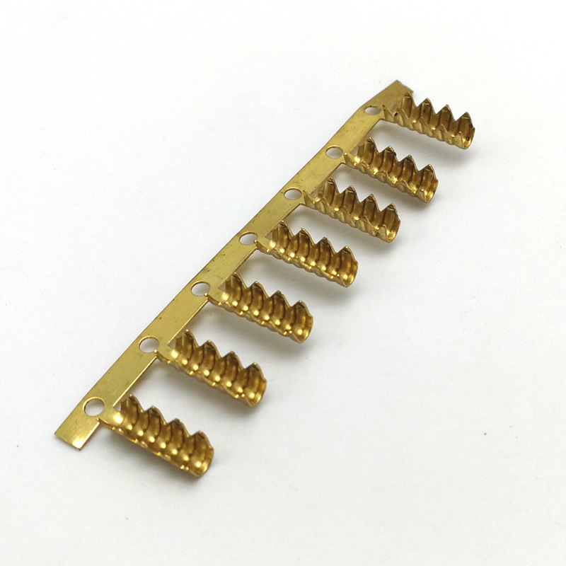
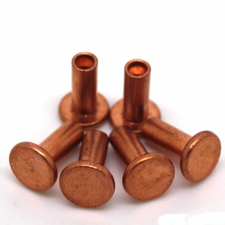
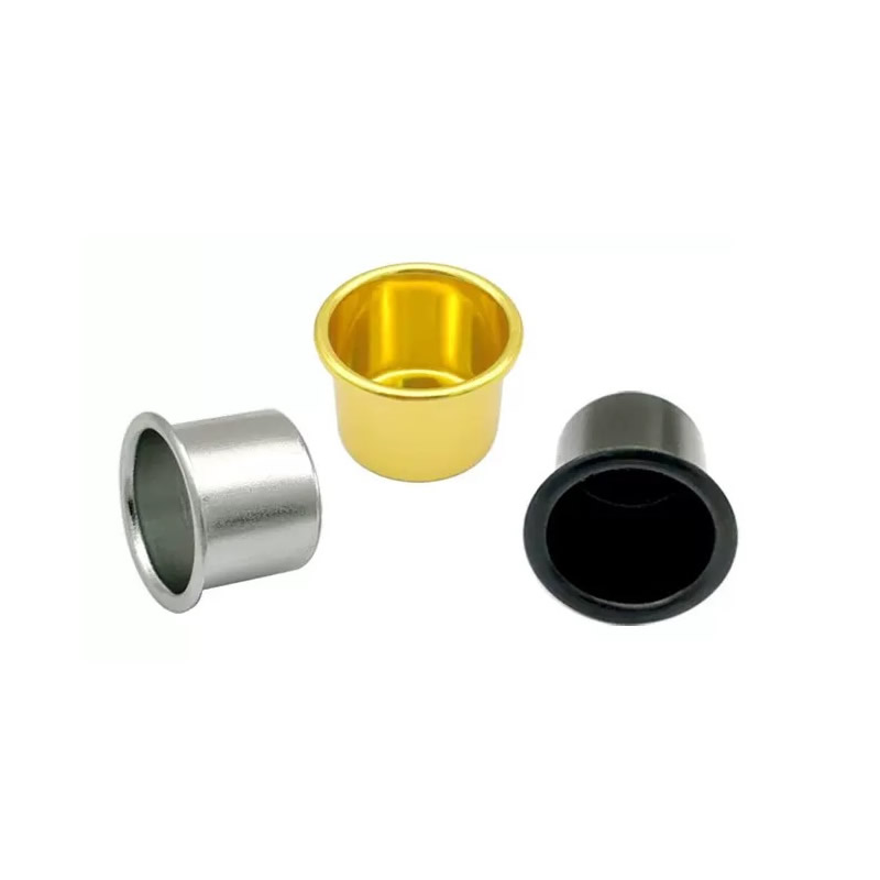
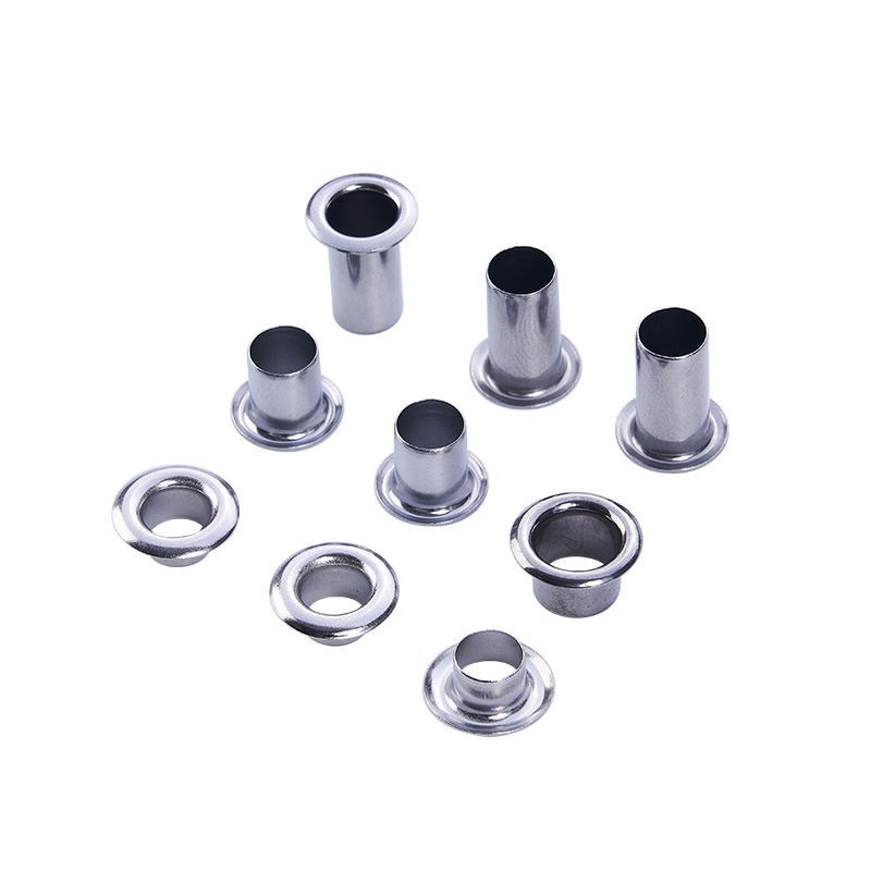
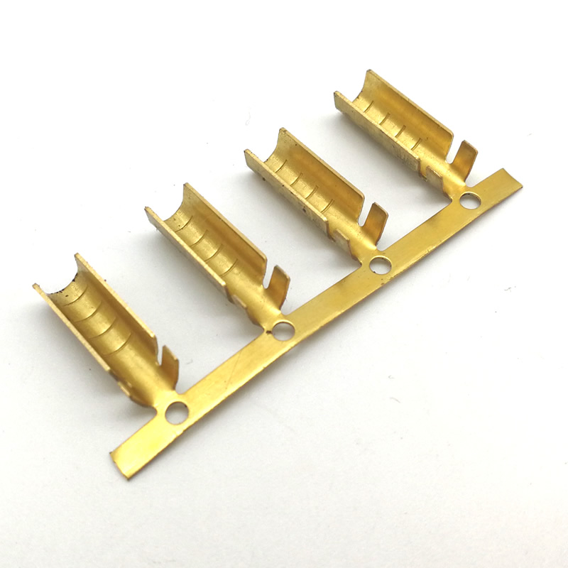
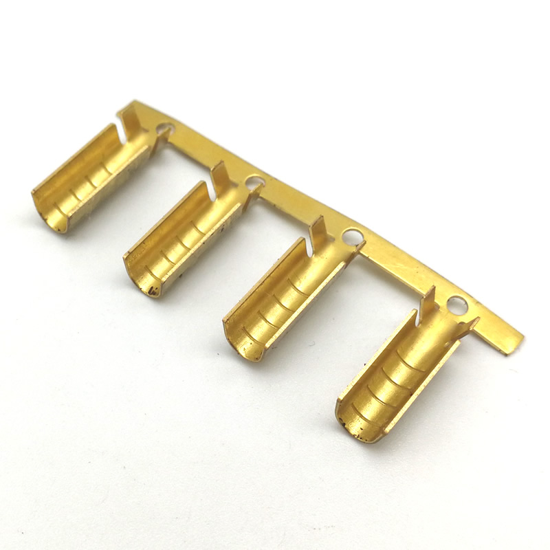
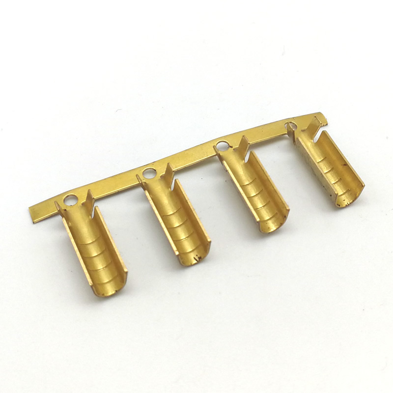
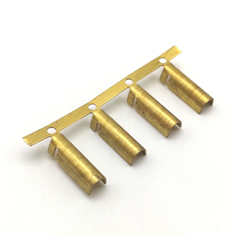
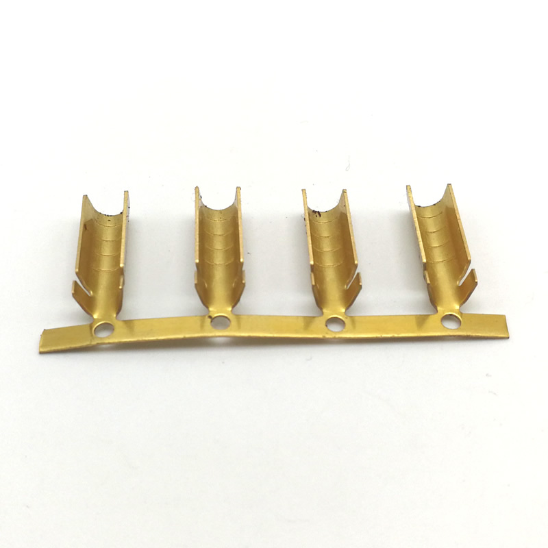
U Type Crimp Terminal
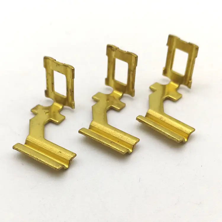
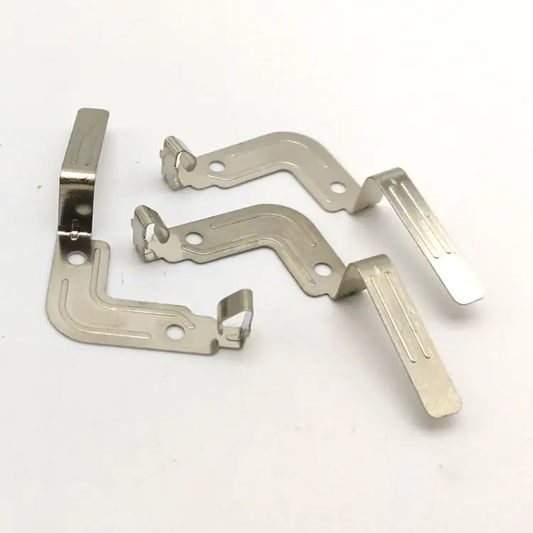
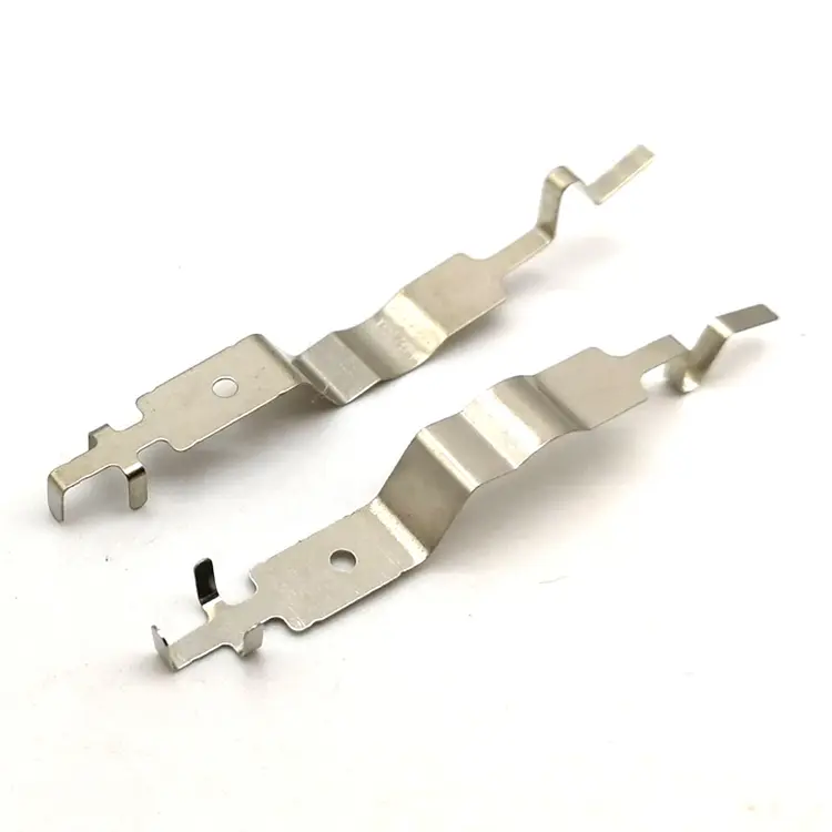
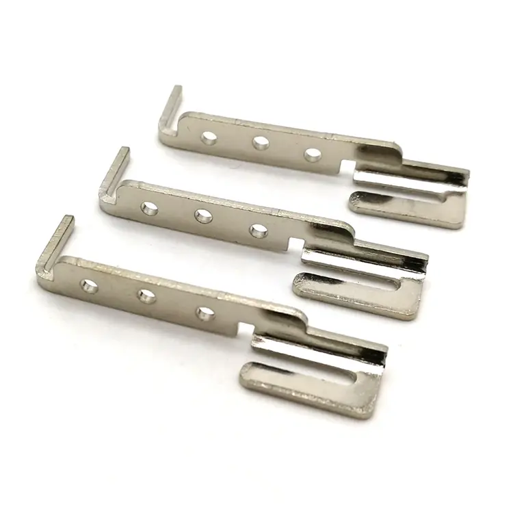
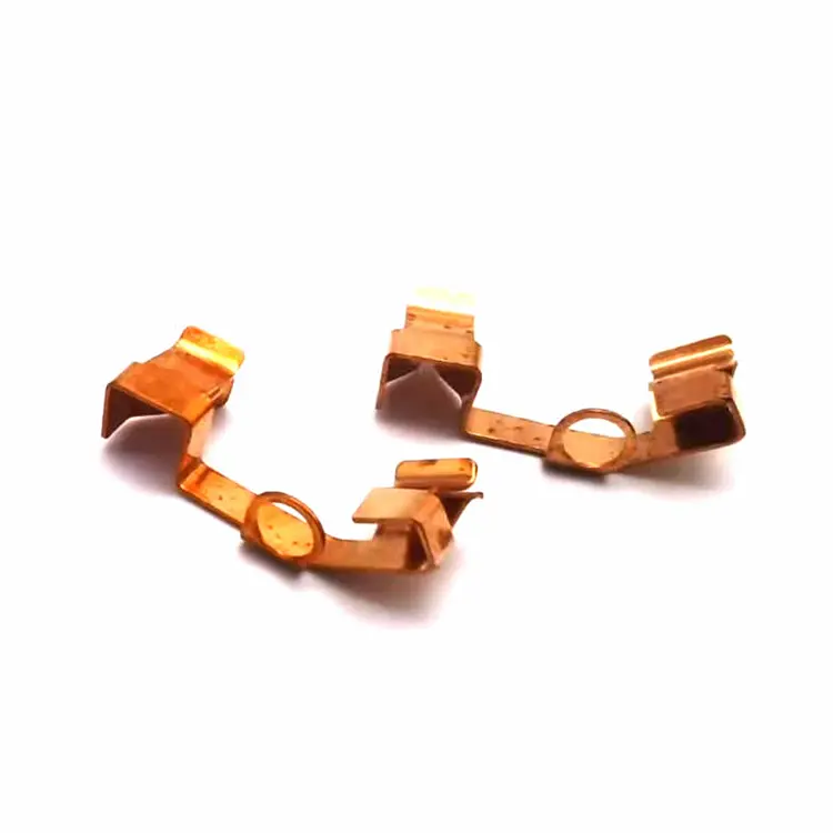
A U type crimp terminal is an open-U connector—the wire drops into the U, and a upper and lower die compress the walls around the strands. The U-opening width, the U depth, and the post-crimp height decide whether the connection holds or the wire pulls out. Nuote Metals produces U type crimp terminals in China with opening geometry and post-crimp height verified per IEC 60352-2. Copper and brass, tin plated.
Send Inquiry
Product Description
U Type Crimp Terminals – The Open-U Geometry Defines the Crimp
A U type crimp terminal is not a closed barrel that the wire is inserted into. It is an open U—the wire drops into the channel from above, and a upper and lower die compress the two walls around the strands. The U-opening width, the U depth, and the material thickness determine how the walls fold, how the strands are captured, and whether the crimp holds under pull-force.
U type terminals are used where the wire is laid in from the side—grounding lugs, cable joints, busbar connections, and terminal blocks. They are judged by the crimp, not by the stamping—and the crimp depends on the U geometry, the die profile, and the post-crimp height.
At Nuote Metals, we produce U type crimp terminals with U-opening geometry and post-crimp height verified per IEC 60352-2. This article covers the U geometry, the upper/lower die crimp, the material selection, and what to verify before accepting a shipment.
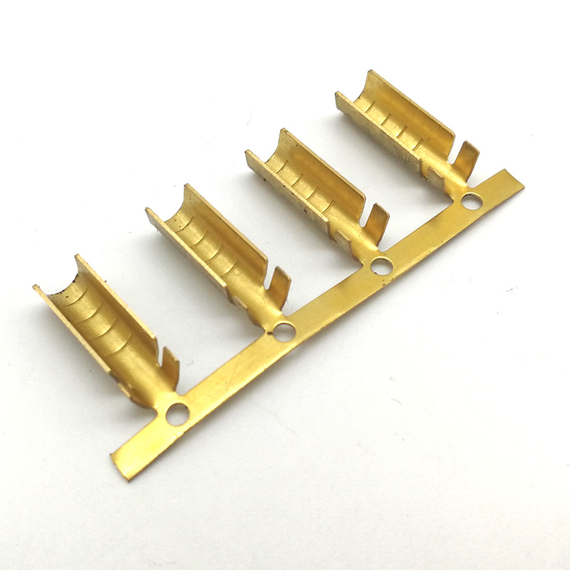
The U Geometry – Three Dimensions That Determine the Crimp
The U is defined by three dimensions—and each one determines how the walls fold around the wire.
| Dimension | What It Controls | Typical Specification | Measurement |
|---|---|---|---|
| U-opening width (W) | Clearance for the wire bundle | Wire diameter + 0.2–0.5mm | Pin gauge, optical comparator |
| U depth (D) | How much of the wire is captured | 1.2–2.0× wire diameter | Depth gauge, cross-section |
| Material thickness (T) | Wall stiffness and current path | 0.3–0.8mm, by current rating | Micrometer |
U-opening width must clear the wire bundle but not be so wide that the walls cannot fold around it. Too narrow—the wire does not drop in. Too wide—the walls fold flat without capturing the strands, and the pull-force fails.
U depth determines how much of the wire circumference is captured. A shallow U captures less than half the wire—the crimp is weak. A deeper U captures more—but if it is too deep, the walls may overlap at the bottom and crack.
Material thickness determines the wall stiffness and the current path. A thin wall folds easily but carries less current. A thick wall carries more current but requires higher crimp force—and may crack at the fold if the die radius is too sharp.
For U type terminals, the U geometry is the crimp specification—not the terminal outline. A terminal that measures correctly on the outline but has the wrong U depth will fail the pull-force test.
Standard reference: Crimp quality is verified per IEC 60352-2 and UL 486A. U-opening dimensions follow DIN 46234 (open U terminals) where specified.
The Upper and Lower Die – Why U Crimp Is Not Barrel Crimp
A barrel crimp uses a four-indent or hex die—the barrel is compressed from all sides. A U crimp uses an upper and lower die—the U walls are folded inward from two sides. The die profile determines how the walls fold.
The upper die is typically a concave or V-shaped profile. It pushes the two walls inward and downward—the walls fold over the wire strands.
The lower die is typically a flat or slightly concave anvil. It supports the U bottom—the walls fold against it, not through it.
The die radius is the critical dimension. A sharp radius folds the wall too tightly—the material cracks at the fold. A generous radius folds the wall smoothly—the strands are captured without cracking.
How we control it: We specify the die profile for the U width and the material thickness—not a standard die for all terminals. For copper U terminals, the die radius is 0.3–0.5mm. For brass, 0.5–0.8mm—brass is harder and cracks at a sharper radius. The die profile is verified by cross-sectioning a sample crimp and measuring the fold radius and the strand compression.
For U type crimp terminals, the die is part of the terminal specification—not a generic tool. A terminal that crimps correctly in one die may fail in another.
Material Selection – Copper vs. Brass for U Crimp
Crimp terminals are made from copper or brass—and the material determines the crimp force, the fold behavior, and the current capacity.
Copper (C11000) is the standard for grounding and power U terminals—highest conductivity, softest, folds easily. But it work-hardens during crimping—the crimped joint is stronger than the annealed terminal.
Brass (C26000, C26800) is harder—it carries less current than copper but resists stress relaxation better. Used in terminal blocks and control panel connections where the temperature is moderate.
The trade-off: Copper crimps easily and conducts best, but relaxes at elevated temperature. Brass resists relaxation but requires a higher crimp force and a larger die radius. For a U type crimp terminal, the material is selected for the current rating and the application temperature—not for the stamping alone.
Plating: Tin plating at 5–10μm, verified by XRF. A plating that is too thick cracks at the fold; too thin, it wears through during crimping.
A Real Example – Pull-Force Failure from U Depth Too Shallow
A German grounding equipment manufacturer needed a copper U type terminal for a 6mm² wire, with a 200N minimum pull-force. Their previous supplier used a U depth of 4.5mm—the wire was not captured deeply enough, and 10% of crimps failed the pull-force test.
What we did differently:
- Increased the U depth to 5.5mm—1.5× the 6mm² wire diameter.
- Adjusted the upper die profile to fold the walls over the strands—not flat.
- Verified pull-force on a sample from every batch—220N average.
- Cross-sectioned a sample crimp—strand compression uniform, no cracks at the fold.
Limitation: This U depth is validated for 4–10mm² wire. Below 4mm², the U depth must be reduced and the die profile re-qualified.
Shipped 1.2 million terminals with zero pull-force failures. This is what U type crimp terminals should deliver: not just a U that clears the wire, but a U that captures the strands—because the opening geometry and the die profile were matched to the wire, not to the stamping convenience.
Frequently Asked Questions
Q1: How do I choose the right U-opening width for my wire?
A: Match the U-opening width to the wire bundle diameter plus 0.2–0.5mm—enough for the wire to drop in, not so wide that the walls cannot fold around it. Match the U depth to 1.2–2.0× the wire diameter—deeper captures more strands, but too deep may cause the walls to overlap and crack. For U type crimp terminals, the wire gauge is the first specification—not the terminal outline.
Q2: What is the difference between U crimp and barrel crimp?
A: A barrel crimp uses a closed cylinder and a four-indent or hex die—the barrel is compressed from all sides. A U crimp uses an open U and an upper/lower die—the walls are folded inward from two sides. The U crimp is used where the wire is laid in from the side—grounding lugs, cable joints, busbar connections. The die profile and the U geometry are different—the crimp result is not interchangeable.
Q3: Why does material thickness matter for U type crimp terminals?
A: The material thickness determines the wall stiffness and the current path. A thin wall folds easily but carries less current—it heats up at full load. A thick wall carries more current but requires a higher crimp force—and may crack at the fold if the die radius is too sharp. For U type crimp terminals, the thickness is matched to the current rating and the die profile—not to the stamping convenience.
Q4: Can you provide pull-force reports and cross-sections with the shipment?
A: Yes. Every batch ships with a pull-force report per IEC 60352-2 and crimp cross-section photos—showing the strand compression and the fold radius. For grounding and power applications, the cross-section confirms that the walls folded around the strands—not flat. The report is part of the PPAP package where required.
Send Inquiry
Please feel free to fill your inquiry in the form below. We will reply you in 24 hours.



X
We use cookies to offer you a better browsing experience, analyze site traffic and personalize content. By using this site, you agree to our use of cookies.
Privacy Policy