
Products
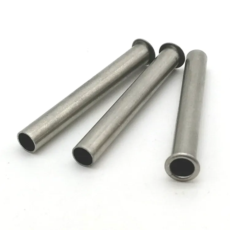

CNC Turning
Nuote Metals offers rapid prototyping service for CNC turning, which enables you to quickly test and validate your product designs, reducing time-to-market and increasing efficiency, as requested by users who need fast turn around.
Send Inquiry
Product Description
Why Tool Geometry and Chip Control Decide Your Surface Finish and Cycle Time
Most buyers focus on the machine when they evaluate a CNC turning supplier. Spindle speed. Axis count. Bar feed capacity. Those things matter. But they are not what determines whether your part comes out with a mirror finish or a torn surface. They are not what causes a crash or a broken tool.
The difference is in two things that rarely appear on a spec sheet: tool geometry and chip control. A lathe with the right angles cuts cleanly and produces short, manageable chips. The same lathe with the wrong angles rubs, work-hardens, and wraps long stringy chips around the tool. The part may still meet tolerance—but the surface finish suffers, the tool life drops, and the cycle time increases.
At Nuote Metals, we treat tool selection and chip management as core engineering decisions, not operator preferences. In CNC turning, these two factors decide whether your part is produced profitably or at a loss.

Tool Geometry – The Angles That Determine Cut Quality
A turning insert is not a generic piece of carbide. It has specific angles that determine how it enters the material, how it breaks the chip, and how it distributes heat. Here are the angles that matter most:
Rake angle. The rake angle controls how aggressively the tool cuts. A positive rake angle has a sharp edge that slices into the material—ideal for soft, gummy materials like aluminum and copper. A negative rake angle has a blunt edge that pushes into the material—better for hard, brittle materials like hardened steel and cast iron. Using the wrong rake angle on the wrong material causes built-up edge, poor finish, or tool fracture.
Clearance angle. The clearance angle prevents the tool from rubbing against the workpiece. Too small, and the tool rubs, generating heat and work-hardening the surface. Too large, and the cutting edge becomes weak and prone to chipping. For stainless steel, we use a larger clearance angle to reduce rubbing and work-hardening.
Nose radius. The nose radius affects surface finish and tool strength. A larger nose radius produces a smoother finish but increases cutting forces and can cause vibration on thin-wall parts. A smaller nose radius reduces forces but leaves a rougher finish. For finishing passes, we use a larger nose radius; for roughing, a smaller one.
Chip breaker geometry. This is the feature that determines chip shape. A chip breaker that is too aggressive produces short chips that can jam the tool. Too passive, and the chip wraps around the part. We select chip breaker geometry based on material, depth of cut, and feed rate—not just what is in the tool crib.
Chip Control – Why Long Chips Cost You Money
A chip that wraps around the tool or the part is not just an inconvenience. It costs money in three ways:
Surface damage. A long stringy chip dragged across a finished surface scratches it. On a sealing surface or a bearing journal, that scratch becomes a leak or a wear point. For parts that will be anodized or plated, a scratched surface becomes a visible defect after coating.
Tool failure. A chip that wraps around the tool shank insulates the cutting edge, raising temperature and accelerating wear. In severe cases, the chip packs into the insert pocket and cracks the insert.
Operator intervention. A machine that stops every few minutes to clear chips is not producing parts. For high-volume production, chip control is the difference between a stable process and a constant interruption.
We control chips through three variables:
Feed rate: Higher feed rates produce thicker chips that break more easily.
Depth of cut: Too shallow, and the chip rubs instead of shearing.
Coolant pressure: High-pressure coolant (70–100 bar) directed at the cutting edge breaks chips and flushes them away from the work zone.
How We Match Tooling to Material
Different materials require different tooling strategies. Here is how we approach the most common materials in CNC turning:
| Parameter | Specification | Test Method |
|---|---|---|
| Material grade | AISI 304 (UNS S30400) | Mill certificate + XRF |
| Shaft diameter | 5.0mm (±0.05mm) | Laser micrometer |
| Length under head | 32.0mm (±0.10mm) | Digital calliper |
| Head diameter | 9.5mm (±0.15mm) | Optical comparator |
| Head height | 1.6mm (±0.10mm) | Digital calliper |
| Tensile strength | ≥520 MPa | ASTM E8 |
| Hardness | ≤90 HRB | ASTM E18 |
| Salt spray resistance | ≥72 hours (no red rust) | ASTM B117 |

A Real Example – Stainless Steel Shaft with Chip Control Problem
A North American hydraulic equipment manufacturer needed a 316 stainless shaft with a 0.01mm diameter tolerance and Ra 0.8μm surface finish. Their previous supplier delivered parts with torn surfaces and inconsistent finish—the chips wrapped around the tool and scratched the part during turning.
What we did differently:
- Switched to high-positive rake inserts with AlCrN coating—sharper edge, less rubbing on 316.
- Increased feed rate to thicken the chip and promote breaking.
- Applied high-pressure coolant at 70 bar directed at the cutting edge.
- Shipped 4,000 pieces with zero surface defects. The customer eliminated incoming polishing and reduced lead time by 6 days.
Frequently Asked Questions About CNC Turning
Q1: Why does my turned part have a torn or smeared surface finish?
A: A torn or smeared finish is usually caused by built-up edge or rubbing. The tool is not cutting cleanly—it is pushing or welding to the material. Common causes include the wrong rake angle, a worn insert, insufficient coolant, or a feed rate that is too low. For gummy materials like aluminum and copper, use high-positive rake and uncoated polished inserts. For stainless, use a sharp edge with high-pressure coolant. At Nuote Metals, we match tool geometry to material to prevent these defects at the source—this is fundamental to any CNC turning process.
Q2: How do I know if my turning supplier is using the right tooling?
A: Ask them three questions: (1) What rake angle do you use on this material? (2) What chip breaker geometry? (3) What coolant pressure? A supplier who cannot answer these questions is not controlling their CNC turning process. A supplier who gives a generic answer—"we use positive rake on everything"—is not matching tooling to material. Nuote Metals documents tooling selection for every part number and includes it in the setup sheet.
Q3: Can tool geometry reduce cycle time?
A: Yes. A tool with the correct geometry cuts faster because it can take a deeper depth of cut and a higher feed rate without failing. A tool with the wrong geometry forces the operator to slow down to avoid chatter or tool breakage. For a typical stainless steel part, optimizing tool geometry in CNC turning can reduce cycle time by 15–25%. This directly reduces unit cost. Nuote Metals reviews tooling strategy during process planning—not after the first batch runs slow.
Hot Tags: CNC Turning,China CNC Turning,CNC Turning Prototype
Send Inquiry
Please feel free to fill your inquiry in the form below. We will reply you in 24 hours.





X
We use cookies to offer you a better browsing experience, analyze site traffic and personalize content. By using this site, you agree to our use of cookies.
Privacy Policy